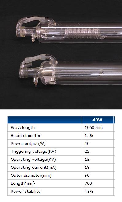
The tube will be the last thing installed, the machine should be in a semi-permanent state (location and orientation) before installing it as we would need to uninstall it to relocate the machine. For the majority of what is left in this build, I think we should follow the order and steps in the google doc but I think we should install and align the mirrors and lens before installing the tube.
Instructions for installing the tube begin at the middle of page 16 on the google doc. This is reproduced below.
Install Tube
- Carefully slide the tube in from right side.
- Once the tube is in the proper location, turn the adjustment screws by hand to center the tube.
- The screws should just contact the tube so it cannot move. Do not put any pressure on the tube. I don’t know how much pressure the tube can take, but you can probably easily break the tube by light hand pressure alone.
The threads in the tube bracket tend to be tight so it does take some strength to get then in, just make sure that is not going against the tube. I like to point my water fitting up so bubbles tend to get washed out easier.
Attach Water Supply.
The cooling system is located outside the enclosure and it provided by the user. It can be a special designed system with radiators and fans or simply a large bucket. The tube is about 20% efficient at full power so multiply the tube wattage by 5 or more to determine how much power you need to dissipate.
Your tube documentation should say how much coolant flow is required. When choosing a pump, be aware that the flow stated may be without and restrictions. You may need to oversize the pump a little. In general most people use cheap submersible pond pumps. The easiest way to measure the flow is to run the water through the system and into a bucket of known volume. Time how long it takes to fill the bucket and do the math.
Wire tube
Tube construction varies, so you should refer to the documentation that came with your tube and power supply to make sure these instructions comply with the requirements of your parts. There are many wire attachment talked about on the buildlog.net forum. The only universally agreed item is that you should never attempt to solder to the electrode on the tube. It will crack the tube or destroy the seal. I like to bind the power supply wires to the using very fine wire.
- Get some bare tinned copper wire in the 34 awg range about 4 inches long per electrode. I usually get it by stripping stranded wire and using one of the strands.
- Tie one end of the thin wire to the tube electrode at the beam exit end.
- Strip the ground wire from your power supply to the same length as the exposed part of the electrode. You may need to extend this wire. This is OK to do using wire of similar gauge, but never extend or splice the positive wire from your power supply.
- Lay the stripped portion of this wire along side the tube electrode and use the fine wire to bind the wire together. Keep it tight and work your way to the end of the electrode.
- Wrap the connector with tape. I strongly recommend silicone self fusing tape.
- Repeat the process for the positive lead from the power supply to the mirror end of the tube.
Test grounding of frame
Give the frame another test to make sure it is grounded. You want to make sure that if any dangerous voltages contact the frame they are shorted to ground through the frame and not through a person touching the frame.
Test Tube
Danger warnings here….
If this is your first time, you are going to be amazed at the power of the beam. It will instantly burn anything in it’s path. Be very careful.
- Fire at a target like a thick piece of wood. Keep it close enough to the tube so it is sure to hit the target, but far enough away so smoke or debris will not contact the exit mirror of the tube.
The instructions go on to cover mirror installation and alignment. These are covered in the Optics section of this project page.
The ammeter to monitor the current through the tube needs to be installed on the negative side of the tube or it will be floating at high voltage – http://www.buildlog.net/wiki/doku.php?id=2.x:wiring_the_tube
Noise needs to be taken into account in deciding on placement of the power supply with respect to the interface PCB. The interface PCB user guide has some suggestions.
Electrical Noise.
The stepper drivers can react to pulses of 1uS and possibly less. This makes them sensitive to electrical noise. There are multiple features on the board to reduce noise susceptibility, but lasers are a very noisy environment. The laser tube and tube power can create enough noise that the drivers can assume a step pulse has arrived and step the motors. Common sense layout of the electronics can reduce the noise getting to the board and prevent any problems. Below are some guidelines you should follow. The Laser Driver PCB has been tested with most of the items below deliberately violated and still performed adequately, but some people may have different results.
-
Place the tube power supply as close to the tube and as far away from the any other electrical items.
-
A metal barrier between the tube power supply and other electronics will help. Steel is better than aluminum.
-
Make sure the laser power supply is well grounded.
- Minimize the length of the tube positive lead and to not run it near any other wiring.
-
Wrap the tube ground wire around the positive lead wherever possible. Be sure keep the ground wire at least 3″ from the tube positive terminal.
-
Keep the 24V power supply lead as short as possible. Consider using a coaxial cable with the center conductor being positive.
-
Use a shielded cable for the laser power supply control cable. Ground the shield at one end only.
-
Twist together any wires that are not shielded.
We can test the laser and power supply separately from the interface control board once it has been mounted – http://www.buildlog.net/wiki/doku.php?id=2x:testing_laser_power_supply

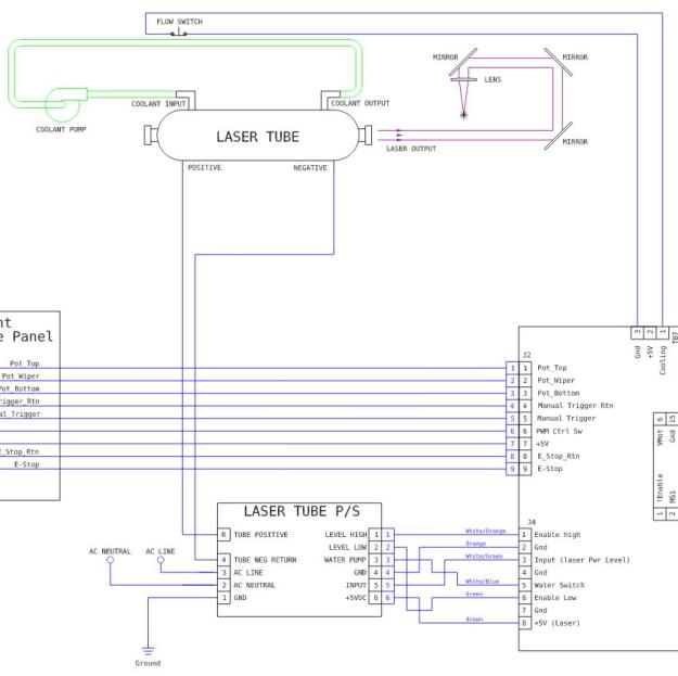
The wiring to the power supply from the interface PCB is via a connection ( J4 ) in the interface diagram. The connections between ( J4 ) and the laser tube power supply can be seen in the buildlog rev 2 schematic.
There is a difference in this buildlog schematic with regards to the interface PCB that we have. In this schematic the water monitor switch is controlled by TB7. In our interface, it is similar but labeled TB4. Additionally, the “cooling” line ( TB7-1 ) which is ( TB4-1 ) on our PCB is in series with the cover limit switch and the emergency stop switch.
These buildlog revision schematics all differ slightly from our setup but collectively have diagrams for each part of ours.


