Featured post

Keep it Local RVA – web app for restaurants in Richmond, VA

Visit the Keep it Local RVA Web App

With all the “gig economy” delivery services available – GrubStreet, EatHub, PostDash, DoorMates, whatever… Restaurants have been losing out on a lot of income.

Many of these restaurants have their own online ordering systems and delivery drivers that are available without the 30% or so cut taken straight from them by these predatory companies.

There is plenty of information available regarding the unethical behavior of these services towards their employees contracted workers and the restaurants they provide for.

The point of this website is to offer direct links, aggregated in one location, to restaurants own services when available. Restaurants without their own services will be included but users are encouraged to order off their menu via a phone call.

kilRVA.com

I know you don’t like the name, but maybe you’ll remember it?

https://kilrva.com

It is hard to get the web app to show up in google search results due to the format of the content. I have created a landing page to optimize for search results and redirect people to the app. Sorry about the name but I paid $12 for the domain and I’m keeping it.

More Laser Progress

The laser is fully operational.  Some additional modifications and additions will be made before the skins are installed.  When the DB-9 connector breakout boards were rewired, during the desoldering of the stranded wire that was used initially, some of the pads got lifted and I couldn’t make a connection to the trace.  I ended up having to solder some of the wires directly to the pins.  I got new DB-9 breakouts with screw terminals instead and installed the male one.  Some communication error between me and Michael regarding ordering females over the internet caused a delay in the acquisition of the female one but it has now arrived.  I will install that in the next couple of days.

Mach 3 is controlling it but I have only cut things using a little workaround for using g-code that was generated for a router via cambam or makercam.  This involves setting the z axis control output to the laser trigger pin.  If you make your toolpaths with the minimum but nonzero cut depth, safety height, and step down increment, there is very little delay between turning on the laser and moving.

There is still an issue with the nozzle for the air that needs to be worked out.  The threads for the set screw may need to be redone.  It is hard to get the nozzle aligned properly and the set screw to hold it in place firmly.  If the nozzle isn’t aligned it interferes in the path of the beam and causes the focused beam to be smeared out or blocked entirely.

Additionally, a switch for the PWM control option needs to be put on the front panel and the power wiring needs to be finished for the back panel so everything runs off of just one plug.  At the moment, the high voltage power supply and the supply for the interface board and water pump are running off the din rail.  So any time the laser and interface board are powered on, the water is running.  The air compressor needs to be plugged in separately to the power bar that is running the computer.  Do not fire the laser without air running or you could damage the lens.  The radiator fans for the water aren’t currently plugged in, but I’m going to take some temperature measurements of the water while it is running to determine if that will even be necessary.

The potentiometer control for the power currently allows you to put more than 20 mA through the laser while running it.  It is rated for 18 mA continuous current and while putting more through it wont blow it up or anything, it will reduce the lifetime of the tube.  I am going to install some additional series resistance to the potentiometer control circuit to limit the maximum allowed current to 20 mA.

Here’s one of the first good cuts, it’s kind of hard to get good pictures of clear acrylic though.

laserlogo4small

laserlogo3small laserlogosmall

NES controller for PC via Arduino

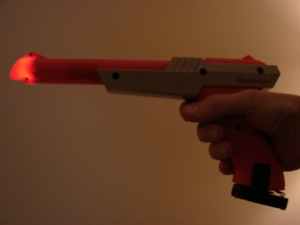
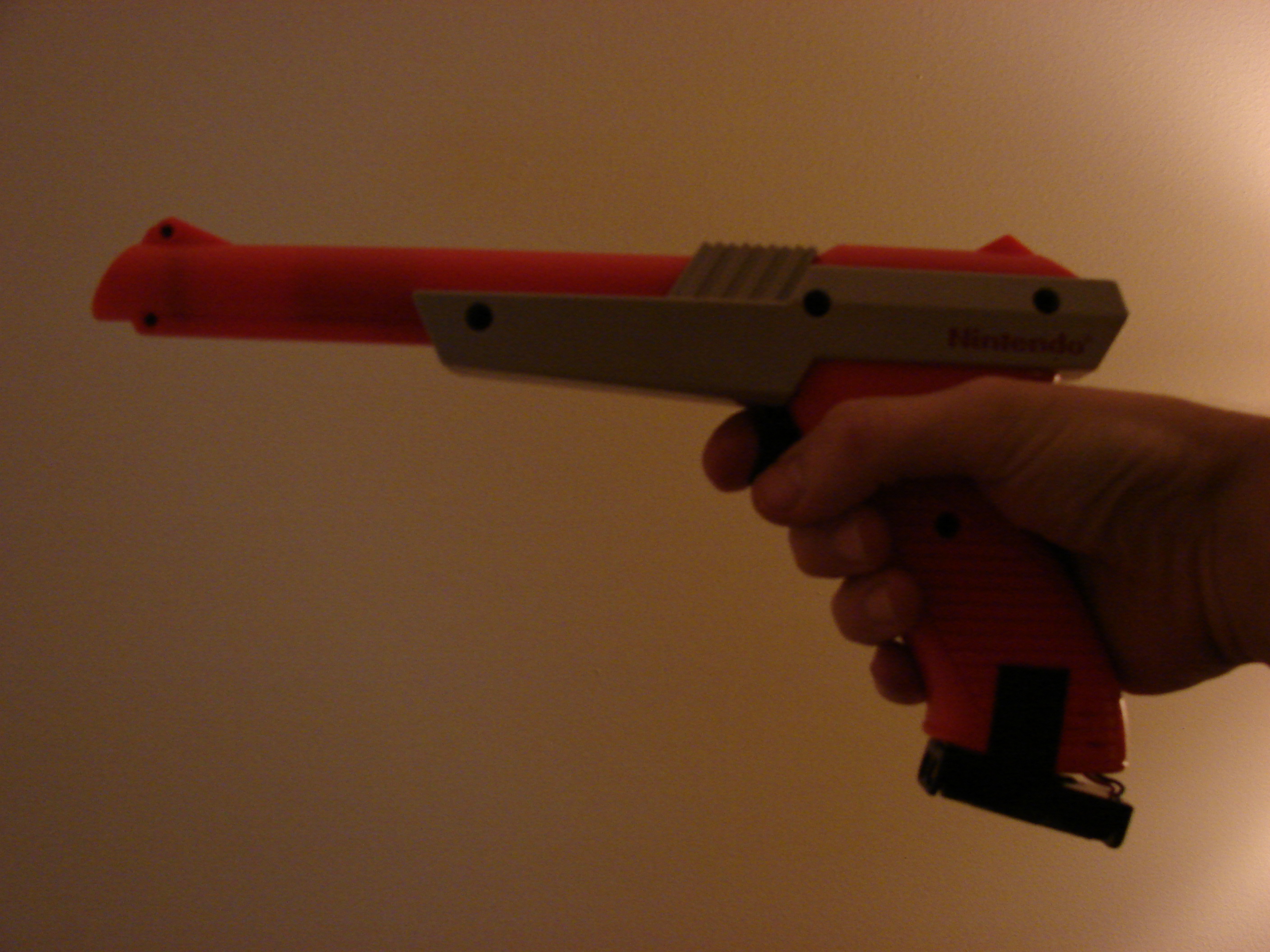
I’ll be updating the 2.x Laser build soon, but I got a little sidetracked while working on it.  The laser is going to have a manual trigger for calibration purposes.  I decided to use a NES zapper because, well, I can.  So in testing the zapper as a switch I added some LEDs and made this (sorry for potato quality pictures):

DSC04524

DSC04526

DSC04528

Then I got really sidetracked with how the NES controller works and decided to mess with it.  Using the same timing that the NES uses to interface with the controller (found here), I wrote an Arduino sketch to get the input.  The shift register will respond to a wide range of timing on the pulses, but I decided to use the exact timing that the NES uses so that I can try to use other methods of input through the Arduino to the NES (that will be a future project, voice control? kinect?).

I also found this post where he uses a library someone created, but that seems kind of unnecessary.  Besides, the sketch I wrote was made to work with a program written in processing for converting the serial output to keyboard commands.

NEScontroller_pinout

This is a better picture of the pinout.  What was labeled “Pulse” in the other link is “Clock” here, and “Latch” is “Strobe”.

Now here’s how to make it work as a controller for an emulator or anything else. this instructable explains how to use an N64 controller via Arduino and a program written in processing.  In the instructable, he claims that if you are using a newer version of processing (newer than 1.0), that you need to import a few extra packages.  I found that with processing 2.2.1 in addition to the packages mentioned, you also need to import the KeyEvent package.  Here’s a link to the same program with all the necessary packages imported.

https://www.dropbox.com/sh/k9upeif77zrsdll/AACvHLZ6ANmZ9b3LDDP-0H5Ka?dl=0

It is possible to just stick some wires in the NES controller output socket and go straight to the arduino.  I found this method to result in somewhat loose connections so just to be safe I used the connector from the NES itself and wired from there (the breadboard looks more cluttered than it should because I was moving stuff around).

arduinoNES

The processing program was modified from one that was originally made to interface with a gamecube controller.  Instead of modifying it again to make it work with an NES controller (we’re going backwards apparently), I just left it as it is and made the NES controller output from the Arduino match the format of the N64 controller output.  My arduino sketch is here:

https://dl.dropboxusercontent.com/u/27794628/NES_Arduino.ino

Run this arduino sketch, then run the processing sketch and make sure the serial port is the same: “You might need to change the line String portName = Serial.list()[1]; to match the your Arduino, it should be either Serial.list()[0]; Serial.list()[1]; or Serial.list()[2];”   This should result in a working NES controller for your computer.

Of course after I do all this I find an easier method: https://gist.github.com/j-mcc1993/8202522

But, my effort was not entirely wasted.  The keyboard library only works on the Arduino Leonardo, Micro, or Due apparently so it wouldn’t have worked on my Uno anyways.  Other methods that I have seen involved updating firmware and more complicated things.  The method I have here is pretty straightforward and easy.

And now I made an Instructable for it so people can actually find it if they are looking: http://www.instructables.com/id/Using-an-NES-controller-for-emulators-with-Arduino/

Laser progress

Last weekend I looked over the stuff that I was still unsure about for the laser.  I found the nozzle for the air assist and Aaron drilled and threaded a hole in it for the set screw.  I wanted to get the wiring done for the limit switches but there was a class going on that made the equipment inaccessible.

This weekend I want to get a couple things done.
1. Wiring for the limit switches (first thing in the Wiring section).
2. Design and cut (CNC) a front panel (first thing in the Additional Notes section).  I will use a thin piece of wood to test it and then we can cut a metal one with the new CNC machine once that is running.  We also need to decide exactly what will be on the front panel.  There are several options covered in the two sections linked above.
3. Adjust belt tensions (#6 in Additional Notes).

As far as things that we still need that we either don’t have or I can’t find, this is the current list.
1. Air pump.
2. Tubing to connect water pump to laser tube.
3. Potentiometer for laser power control (for front panel).
4. Air pump switch (for front panel).
5. Bed/Platform for placement of things to be cut.
6. Optional items for front panel – key switch, button switches for manual firing, pwm control switch.

2.x Laser

This is mainly intended for hack.rva members that are interested in finishing building the laser.  I made a page with a bunch of sub-pages to organize what is left of the build.  If anyone has input you can email me or just comment on this post (I don’t think you can comment on the actual page).

2.x Laser Build

If any random internet person that stumbles across this has any constructive feedback or input on the project, especially if you have done something similar, feel free to comment here on this post as well.

Pendulum Waves

Back when this video was making its rounds on the interwebs (it periodically resurfaces but its popularity seems to be dying out, perhaps behaving like a damped harmonic oscillator), I did a little project explaining the motions involved.

https://dl.dropboxusercontent.com/u/27794628/pendula5.html

It appears something got wonky with the transparency options but everything else seems to work fine.  If you click and drag on the animations you can rotate them in 3D.  Try adding a bunch of extra pendula if your computer can handle rendering it.

GaN Photoluminescence

I was looking through some old files and I found some real (boring) physics!  Here’s some lab work that I did a couple years back if you want to see what comes of shining lasers on things in a lab.  This is why I don’t want to do research in solid state/material physics.

https://dl.dropboxusercontent.com/u/27794628/lab3blog.html

https://dl.dropboxusercontent.com/u/27794628/lab4blog.html

I do recall a somewhat interesting story regarding that second paper though…  My professor was a referee as a part of the peer review process for some physics journal, and he was sent several papers on GaN as he was somewhat of an authority on the material.  One of the ones he rejected was due to this very effect that is examined in the lab paper.  The author of the rejected paper didn’t understand the cause of the oscillations and kind of fudged the data in an attempt to say it was consistent with phonon oscillations.  The professor happened to know that these types of oscillations should not occur given the particular experimental setup and this lab was devised in part to show that they were in fact due to internal reflections rather than phonon oscillations.  Okay that wasn’t that interesting.


Heat Dissipation in a Ring


In an effort to put some physics content on here, I give you heat dissipation in a ring.  It starts off with a non-uniform heat distribution, as indicated by the color gradient on the ring, and eventually the heat dissipates as it goes toward equilibrium.  I made this a while back while studying Fourier series, I believe.

Here’s the animation:

HeatRing3

And the code that generated it:

fourierheat

Looking at that mess of code I realize that the whole thing could just as easily be modeled with the temperature being a sine wave as a function of theta in polar coordinates with decreasing amplitude over time.  There was some reason for the specific way it was formulated here that had to do with Fourier analysis.  There were other scraps of code before this part in the Mathematica file that had finite series approximations. I’ll revisit it at some point and see if the reason was useful at all.

Binary Counter

So when I first started messing with electronics stuff I decided to try to understand things starting with the simplest components and working up from there.  I found a binary counter IC and wired together something to convert its binary counting to sequential counting by using transistors as digital logic gates.  I cheated a little bit and used some packaged IC NOR gates but still this is on a pretty fundamental level of digital logic.

DSC05143

The battery connected to the voltage regulator on the left goes to a 555 timer that is just pulsing a signal to the binary counter.  The battery also powers the red LEDs and if I remember correctly the other battery is to power the yellow LEDs because the voltage drop through the 555 and a red LED didn’t leave me with enough for another LED at the same time with the way it was wired. The outputs directly from the counter are displayed on the yellow LEDs and the same outputs pass through all the digital logic crap and light up the red LEDs sequentially.

Using these larger discrete components makes you realize how much goes into these small chips we have even for very simple functionality.  Just the 555 timer itself could be made with the same transistors and resistors I used for the logic parts here.  Take a look at this kit where you can do just that http://www.evilmadscientist.com/2013/555-kit/555 kit And here’s a video of the counter in action.  There’s an episode of Futurama playing in the background providing the somewhat epic commentary.